General-Purpose Input/Output
The Compute Blade allows for the uses of 11 of the Compute Module's GPIO pins. The GPIO allows for low speed modules and additional device control.
GPIO Locations and Functions
Functions are configurable and do not have to match the given functions.
Using internal GPIO for unintended uses may lead to damage.
| GPIO | Location | Functions |
|---|---|---|
| 2 | Expansion Module Port | I2C1 SDA |
| 3 | Expansion Module Port | I2C1 SLC |
| 4 | Expansion Module Port | GPCLK0 |
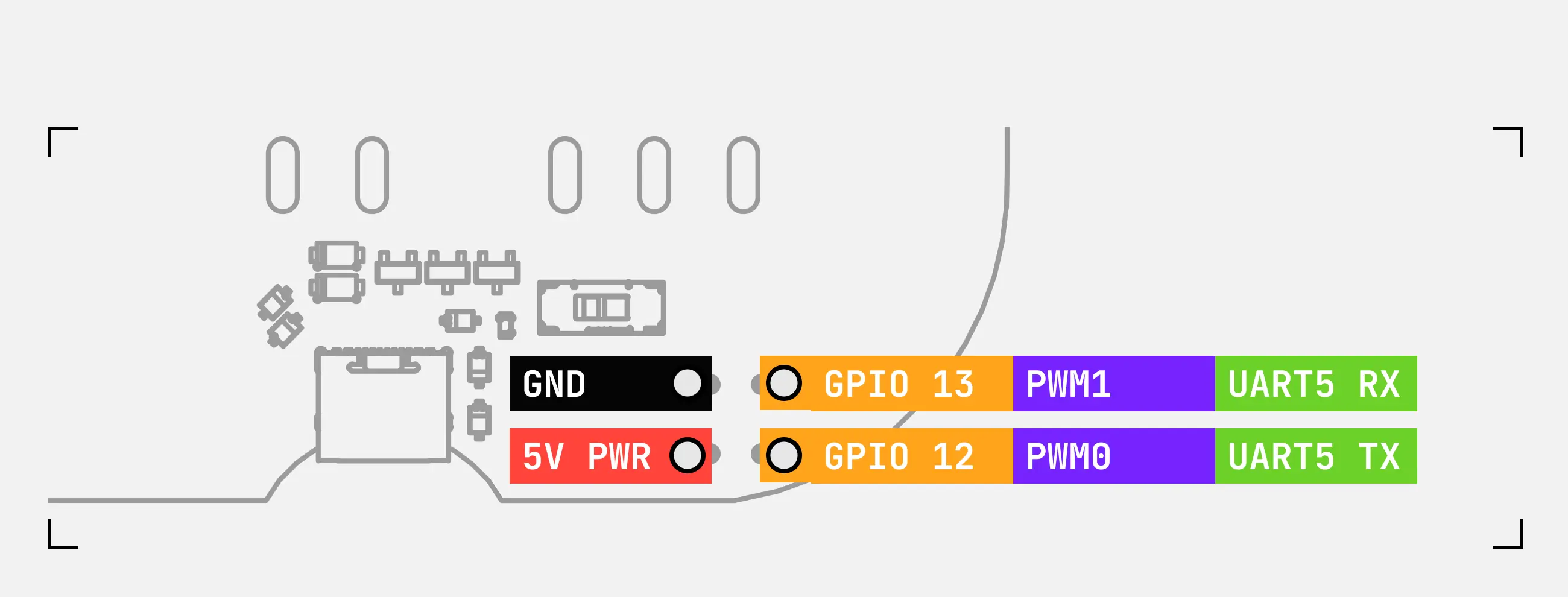
| 12 | Fan Unit Connector | PWM0, UART5 TX |
| 13 | Fan Unit Connector | PWM1, UART5 RX |
| 14 | Expansion Module Port, UART Front(3pin), UART Back(4pin) | UART0 TX |
| 15 | Expansion Module Port, UART Front(3pin), UART Back(4pin) | UART0 RX |
| 18 | Internal | LEDs Control |
| 20 | Internal | Edge Button |
| 21 | Internal | LED Control |
| 23 | Internal | PoE+ Indicator |
Pinout Guide
View an interactive guide to the full Raspberry Pi GPIO pinout on Pinout.xyz
- Expansion Module Port
- UART
- Fan Unit Connector
The Expansion Module Port is pin 1 through pin 10 of the Raspberry Pi GPIO pinout.
This makes the Expansion Module Port compatible with many existing products like Real Time Clock Modules or I2C Devices.
Ensure you reference the pinout on your specific Compute Blade and the module's datasheet for correct wiring.
There are two dedicated sets of pins for UART0. The V5 line on UART Back can operate as an Input or Output.


When no power source is connected to the compute blade the V5 pin can only be an input.
The square connector at the end of the Blade.
The main purpose is to connect to a Fan Unit. It can be used to control any 5v PWM fan or as an additional UART port (UART5 on CM4)

