Smart
The Smart Fan unit utilizes the RP2040 microcontroller featured in the Raspberry Pi Pico 1. Using the RP2040's two UART connections, a link can be established to each blade using the fan connectors.
Hardware
Power Delivery
The Smart Fan Unit can be powered with +5V from both Blade Port A or Port B In addition to the USB Type-C for flashing. USB Type-C with not power the fan
LEDs
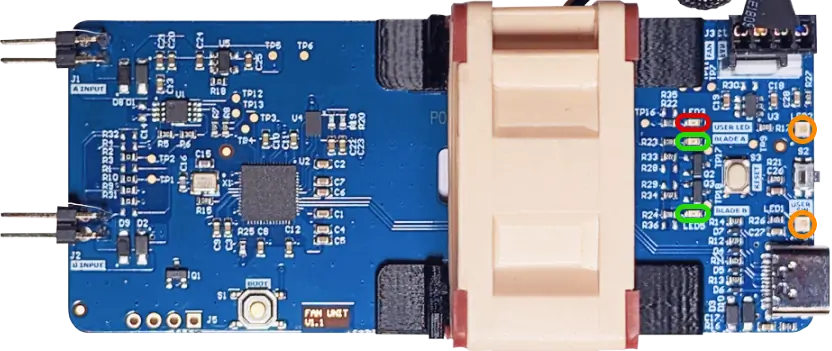
The Smart Fan Unit has 5 LEDs
| LED | Location | Type |
|---|---|---|
| LED1 | Yellow | Programmable NeoPixel at index 0 |
| LED2 | Yellow | Programmable NeoPixel at index 1 |
| LED3 | Red | Green Programmable at GPIO25 |
| LED4 | Green | Blue Power indicator for Port A |
| LED5 | Green | Blue Power indicator for Port B |

Button
A programmable button is located on on the rear of the Smart Fan Unit. It can be addressed at GPIO12
Fan control
The Smart Fan Unit uses the EMC2101 from Microchip/SMSC a fan controller with temperature monitoring. The EMC2101 is connected over the I2C bus to the RP2040
The EMC2101 has two temperature sensors. An internal sensors on the IC(Red) located next to Port A and an external sensors(Green) located next to Port B

Additional information
Pin Out Guides
Smart Fan Unit

Fan Header

J5 Debug Header

RP2040 Pin Reference Table
Pins used by the Smart Fan Unit
| Pins(RP2040) | Functions |
|---|---|
| GPIO1 | UART0 RX |
| GPIO2 | UART0 TX |
| GPIO4 | I2C-SDA |
| GPIO5 | I2C-SCL |
| GPIO8 | UART1 TX |
| GPIO9 | UART1 RX |
| GPIO12 | Button |
| GPIO15 | Two NeoPixel LEDs |
| GPIO16 | Power to Fan |
| GPIO25 | LED3 |
Update Firmware
To start using the Smart Fan Unit, it should first be flashed with the latest firmware of your choice. This could be any custom firmware, or a pre-existing framework.
First, start by removing power from the Fan Unit. Then hold down the BOOT button and connect the USB Type-C to your computer.
The Fan Unit will now appear as a storage device labelled RPI-RP2 on your computer.
The firmware you are flashing should have the file extension .uf2
Move the *.uf2 file into RPI-RP2, it should disconnect after a few seconds and reboot to the newly installed firmware.
CircuitPython
We have prepared example code to help you get started with your Smart Fan unit. Using CircuitPython which is a programming language designed to simplify experimenting and learning to code on low-cost microcontroller boards.
The code has the following basic functionality example :
- Button use
- LED control both Green and NeoPixel
- Fan control based on a simple fan curve
- UART communication
Fan Curve Reference Table
Fan Curve used in example code
| Temp Range | Present Fan Speed |
|---|---|
| t >= 40C | 100% |
| 35C <= t < 40C | 70% |
| 33C <= t < 35C | 60% |
| 31C <= t < 33C | 40% |
| 29C <= t < 31C | 30% |
| 29C < t | 10% |
Installing CircuitPython
- Download the latest version of CircuitPython 9
- With the Compute Blade connected from prior firmware flashing steps, move
adafruit-circuitpython-raspberry_pi_pico-en_US-*.uf2file into theRPI-RP2storage device - It will be disconnected and
LED 3will blink green - The fan Unit with reconnect as
CIRCUITPYwill be connected
Deploying Code example
- Having installed
CircuitPythonand connecting the fan unit to your computer via USB-C - Download the example code from GitHub
- The code should be placed in
CIRCUITPY; if prompted to replace any files, click yes
Enable UART on CM4
To enable UART on the compute blade, open /boot/firmware/config.txt
sudo nano /boot/firmware/config.txt
Instead of the BIOS found on a conventional PC, Raspberry Pi devices use a configuration file called config.txt. The GPU reads config.txt before the ARM CPU and Linux are initialized. Raspberry Pi OS looks for this file in the boot partition, located at /boot/firmware/.
config.txt in Raspberry Pi DocumentationThen add the following lines:
[cm4]
enable_uart=1
dtoverlay=uart5
Reboot the the Compute Blade. When it has restarted, the UART connection will be available at /dev/ttyAMA5
Debugging
There is an unpopulated pin header labelled J5 located below the B port on the Fan Unit.
Debug pins

These debug pins can be used with a tool like the Raspberry Pi Debug Probe to debug and program the RP2040.